Acustica architettonica en
Da "Fisica, onde Musica": un sito web su fisica delle onde e del suono, acustica degli strumenti musicali, scale musicali, armonia e musica.
Jump to navigation Jump to searchThe general problem of environmental acoustics
When we listen to sound produced by a sound source (e.g. an orchestra) in a closed environment the sound field perceived by the listener is made up of two contributions:
- direct sound , which is a sound wave that reaches the listener directly from the source. Obviously, this direct sound only exists if there are no obstacles between the sound source and the receiving apparatus of the listener (e.g. their tympanum);
- reflected sound, which reaches the listener only after having been reflected (even multiple times) from the walls, floor and other obstacles (e.g. the chairs, the audience). Obviously, this sound will reach the listener with a certain delay with respect to direct sound and will create a "sound tail" that persists even after emission from the source has ceased.
Just from these quick considerations, we can already clearly see the general problem of environmental (and architectural) acoustics:
- under what conditions does the superposition of direct and reflected sound allow us to define an environment with good acoustics?
- and what are the physical and perceptive parameters that define those good acoustics?
- Are they subjective or objective?'
The first solution might be to eliminate reflected sound entirely. This can be achieved by completely covering the walls with phono-absorbent material. However, this solution is too drastic, as it would impoverish the sound by removing the inimitable charm of the 'live' effect. A certain degree of "reverberated" sound is expected and makes sound warmer, more continuous and more fluid. As a test, listen to these audio examples:
|
The first example was recorded with the microphone very close to the instrument in a small environment. The delay time of the reflected sound is almost negligible; therefore, we can consider that the direct and reflected sounds are practically superimposed. The sound is very dry and, despite the musician's talent, it does not seem fluid and continuous. In the second example, the sound was electronically manipulated to recreate the typical "reverberation" of a concert hall. This sound is continuous and surrounded by an aura that gives fluidity and warmth and enlivens the performance. |
|
|
Therefore, a certain degree of reverberated sound is preferred and the solution of eliminating it completely is definitely not optimal. From a theoretical point of view, controlling a reverberated field is a very complex problem for several reasons:
- reflection of sound waves by walls is a complex phenomenon: depending on the frequency of the incident wave, it can vary from specular reflection for high frequencies to diffuse reflection for low frequencies (i.e. wavelengths comparable to the asperity of the reflecting surfaces).
- the geometry of the reflecting walls can create focalisation phenomena of the reverberated field, such as echo and the formation of stationary waves, which would compromise the desired uniformity of the reverberated sound field.
- present in all reflection phenomena are also phenomena of sound energy absorption, which is partially converted into heat by virtue of friction.
The desired homogeneity of a reverberated sound field, which is needed to reach all listeners throughout the hall as uniformly as possible, can be obtained through:
- mirrors and deflectors (usually smooth, rigid wood panels of various shapes), which are placed in "strategic" positions to achieve their effect;
- phono-absorbent panels (panels made of porous material with holes that absorb sound rather than reflecting it) used to damp undesired reverberations and resonances, for example in cinemas, where the power of the loudspeakers is remarkable with respect to the volume of the room.
Reverberation time
The first parameter that serves to study the effects of the "sound tail" generated by reflected waves and their interaction with a direct sound field is reverberation time. It is defined as the time necessary for sound intensity to weaken one million times (-60 dB) with respect to the maximum value reached prior to the release transient.
To have optimal acoustic quality, a compromise must be found between short reverberation times (which guarantee clarity of sound and speech impeding the superposition of sounds and words emitted at different times) and longer reverberation times that give sonority, fullness and liveliness to sound.
It is obvious that a single rule does not exist. Optimal reverberation times will vary depending on the use of a closed environment (conference auditoriums, opera houses, halls for symphonic concerts or chamber music) or the type of music being performed. A subjective evaluation, based on the opinion of a wide sample of experts, claims that, for typical room sizes, reverberation time should be (these values are only indicative):
- short (about 1 second) for lessons and conferences, for which the primary need is the intelligibility of speech; excessive reverberation would lead to the superposition of words and interfere with comprehension;
- medium (from 1 to 1.6 seconds) for opera and chamber music, for which the primary need is the intelligibility of the opera libretto and the fine structure of romantic and baroque music; however some reverberation is always welcome for the usual reasons;
- long (from 1.8 to 2.2 seconds) for symphonic music, for which the primary need is an enveloping sound that can unify sounds coming from all the orchestral instruments thanks to multiple reflections;
- very long (3 seconds) for organ concerts and liturgical chants (e.g. Gregorian chants), for which the long words and chords do not create problems of intelligibility even for long reverberation times.
Some examples of electronically created reverberation
Starting from a "dry" sample (recorded in an almost anechoic environment), we have electronically manipulated the sound to reproduce several reverberation conditions and highlight their impact on perception. Even though the reverberation effect is evident in these examples, it is not often consciously perceived by a non-trained ear in normal listening conditions. A certain quantity of reverberation is always present in all environments and, therefore, we hardly notice it simply because it is a "natural" property. Reverberation helps to create a feeling of volume in a surrounding environment, along with visual perception which is generally dominant. Actually, the more reverberation has a negative acoustic impact, the more it is noticed. This happens, for example, in environments in which speech becomes unintelligible due to an excess of reverberation or, at the extreme opposite, in an anechoic room in which there is an absence of reverberation. This environment is often perceived as unnatural, even unpleasant, and causes discomfort to the human perceptive system.
| sound | comment | |
|---|---|---|
|
The "dry" sound is similar to what we would hear up close to an instrument in an environment with little or no reverberation, such as a recording studio. | |
|
We left the original sound level the same and added a reverberation tail that simulates a small environment (15 m²) with fairly reflective walls (reverberation time is 1 s). | |
|
We enlarged the environment somewhat (30 m2) and lengthened the reverberation time (to 2.5 s). This would correspond to an undecorated, medium-sized room with a high ceiling. Then, we lowered the original sound level with respect to the reverberation tail level, which simulates what we would hear being at the end of a larger room with the same reverberation. | |
|
We mixed the two preceding files and then separated them into right and left channels. This situation would correspond to listening to music in a large room while being close to the source and turned at a 90° angle to it, so that the left ear is closer to it while the right ear can better hear the delayed response of the room. |
What does reverberation time depend on?
We would expect that reverberation time, as it is defined, would depend on:
- room volume (larger rooms force reflected sound to make longer "crossings" and, therefore, increases reverberation time);
- the absorbing power of the walls and furnishings including the audience. As reverberation time measures the rate of sound extinction, we expect that highly absorbent walls significantly reduce the number of reflections necessary for reflected sound energy to diminish to 60 dB with respect to the maximum value (i.e. the reverberation time). Since the absorption ability of walls and furnishings varies greatly with the variation of sound frequency, reverberation time will also depend, albeit indirectly, on sound frequency.
- the humidity of the room, especially in large halls, where attenuation of sound energy due to damping is no longer negligible (for more on this, see this page ).
Calculation of reverberation time
A calculation of reverberation time cannot disregard an accurate measurement of the absorption of the walls and furnishings.
-
absorption coefficients α have been determined to quantify absorption by walls of various types of materials, which are a fraction of the energy absorbed with respect to the incident energy. Presented in the table below are adimensional coefficients for the most used materials as a function of frequency (we usually assume that the central frequencies of bands are separated by an octave). The details in the table allow us to observe that:
- reverberation time can be modified by the addition of furnishings (drapes, rugs, vibrating panels, etc.); however, these furnishings must be large enough to avoid being ignored by sound waves due to the phenomenon of sound wave diffraction;
- along with the size of the furnishings, the nature of the absorbent surfaces is also important (e.g. for a rug, the absorption coefficient value is influenced by pile height)
- hard surfaces and even water reflect almost all of the incident energy (the absorption coefficient is close to zero). If our auditory system did not have an ingenious system of "small bones", sound waves hitting our eardrums would barely be absorbed by our cochlear fluid because it would be almost completely reflected;
| Central frequencies in octave bands (Hz) | ||||||
|---|---|---|---|---|---|---|
| Material | 125 | 250 | 500 | 1000 | 2000 | 4000 |
| Openings of ventilation conduits | 0.75 | 0.80 | 0.80 | 0.80 | 0.85 | 0.85 |
| Opening of the proscenium | 0.30 | 0.35 | 0.40 | 0.45 | 0.50 | 0.55 |
| Gravel with a 150-mm thickness | 0.15 | 0.30 | 0.80 | 0.42 | 0.61 | 0.72 |
| Dry sand with a 150-mm thickness | 0.24 | 0.34 | 0.45 | 0.62 | 0.76 | 0.95 |
| Acoustic plaster with a 10-mm thickness applied directly to walls | 0.08 | 0.15 | 0.30 | 0.50 | 0.60 | 0.70 |
| Plaster, marble, tiles | 0.01 | 0.01 | 0.02 | 0.02 | 0.02 | 0.03 |
| Parquet flooring over concrete | 0.04 | 0.04 | 0.07 | 0.06 | 0.06 | 0.07 |
| Flooring in tiles, linoleum, asphalt or rubber over concrete | 0.02 | 0.03 | 0.03 | 0.03 | 0.03 | 0.02 |
| Surfaces of hard, compact structures | 0.02 | 0.02 | 0.03 | 0.03 | 0.04 | 0.05 |
| Strongly vibrating surfaces (wood panels with air gaps, etc.) | 0.40 | 0.20 | 0.12 | 0.07 | 0.05 | 0.05 |
| Lightly vibrating surfaces (false ceilings) | 0.10 | 0.07 | 0.05 | 0.04 | 0.04 | 0.05 |
| Water surfaces (pools) | 0.01 | 0.01 | 0.01 | 0.02 | 0.02 | 0.03 |
| Rugs (with 3.2-mm pile) | 0.05 | 0.05 | 0.10 | 0.20 | 0.30 | 0.40 |
| Rugs (with 6.4-mm pile) | 0.05 | 0.10 | 0.15 | 0.30 | 0.50 | 0.55 |
| Rugs (with 10-mm pile) | 0.09 | 0.10 | 0.20 | 0.30 | 0.55 | 0.55 |
| Velvet drape with over 50% of its surface hanging open | 0.12 | 0.25 | 0.52 | 0.70 | 0.75 | 0.77 |
- absorption due to furnishings is usually expressed by the number S having the dimensions of an area able to absorb (by letting it out of the auditorium) the same quantity of sound energy of the furnishings in question. For the evaluation of the "effective absorption area" of people, consider that the total surface area of an adult of normal stature is about two square metres.
| Central frequencies in octave bands (Hz) | ||||||
|---|---|---|---|---|---|---|
| Material | 125 | 250 | 500 | 1000 | 2000 | 4000 |
| An adult | 0.23 | 0.33 | 0.39 | 0.43 | 0.46 | 0.46 |
| A standing person wearing heavy clothing | 0.17 | 0.41 | 0.91 | 1.30 | 1.43 | 1.47 |
| A standing person wearing light clothing | 0.12 | 0.24 | 0.59 | 0.98 | 1.13 | 1.12 |
| A person sitting on an upholstered chair | 0.25 | 0.35 | 0.40 | 0.40 | 0.40 | 0.40 |
| A wood chair | 0.02 | 0.02 | 0.02 | 0.04 | 0.04 | 0.03 |
| An upholstered theatre seat | 0.04 | 0.13 | 0.22 | 0.17 | 0.16 | 0.11 |
| An upholstered theatre seat covered with velvet | 0.14 | 0.25 | 0.30 | 0.30 | 0.30 | 0.30 |
- It is easy to believe that total absorption can be expressed in terms of "total equivalent area" A equal to:
-
(1)
Ai being the area of the wall with coefficient αi and Sj being the area equivalent to the j-th furnishing.
The first formula for the calculation of reverberation time TR was proposed in 1898 by Sabine, an American physicist and mathematician, considered one of the founders of modern acoustics, [1]
where V represents the room volume and A is the total equivalent area calculated in (1).
This formula, determined using statistical reasoning about the average free path between two reflections, evidently fails due to two reasons:
- when absorption coefficients tend to 1 (as happens in completely absorbent anechoic rooms) reverberation times do not tend to zero;
- it fails when there is a large dishomogeneity of absorption by walls.
The first correction was proposed in 1930 by Carl Eyring with the formula:
in which
is an average absorption coefficient defined as the ratio between the total equivalent area and the surface STOT of the walls. That formula has the advantage that time TR approaches zero when approaches 1. Moreover, it approximates well Sabine's formula for small values of (as we learn in mathematical analysis for small values of ).
A further correction must be introduced to take into account the absorption of sound by air, especially in large halls. In these cases, we add to the absorption factor a term proportional to room volume Therefore, Eyring's formula becomes:
In any case, all the preceding formulae turned out to be not sufficiently accurate when, starting in the 1970s, the problem of calculating reverberation time was dealt with through computer-assisted simulations.
Other factors for "good acoustics"
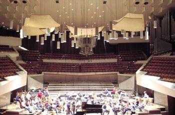
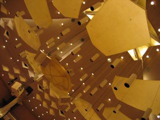
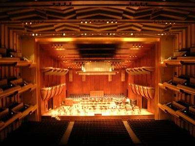
Reverberation time is certainly not the only factor for optimal acoustics in an environment. A case to learn from, which demonstrates the complexity of designing an environment with specific acoustic characteristics, is the Philharmonic Hall at Lincoln Center in Manhattan (image on the right). The designer Leo L. Beranek, in his preface to his monumental textbook on acoustics wrote, ..." "[2]
Even though the room had a substantially correct reverberation time, the acoustic quality was a disaster. The trial and error method, which from the time of Vitruvius, [3] was the only sure guide for a progressive refinement of the acoustic quality of an environment and which Sabine himself had followed with hard measurement campaigns (he worked at night so his measurements would be the least possible effected by environmental background noise), was abandoned by Beranek in favour of theoretic principles that were well-founded but too simple to capture the complexity of real phenomena.
The room had numerous defects, to list only a few:
- an apparent absence of low frequencies; the cellos and basses could barely be heard and were much delayed. It was discovered that the ceiling panels responsible for the first and most important reflections were too small and could not properly reflect the lowest frequencies (see sound defraction); spectators heard the low frequencies only after multiple reflections by the walls and a long delay;
- the members of the orchestras could barely hear each other (the reflecting wall behind them, inherited from the old stage, was too absorbent);
- the wall geometry created phenomena of sound energy focalisation in several points of the room (think of a parabolic mirror that concentrates energy into a focus) and "sound shadows" in other points;
- the room's floor was not very inclined and the sound passed over the spectators' heads. The spaces between the aisles behaved like resonators and curved the low-frequency sound waves upwards. It was a disaster!
The room was later improved at a significant cost (it is now named after the financier Avery Fisher) and remains as a reminder to never abandon experimentation with scale and computer-assisted models.
Stationary waves in closed environments
A possible source of dishomogeneity of a reverberated sound field can come from the formation of stationary waves. As thoroughly explained on the page about resonanting cavities, the confinement of a wave creates stationary waves at a fixed set of discrete frequencies. Frequencies must satisfy conditions of quantisation that, in the case of a parallelepiped room with dimensions A, B and C, are:
The vibration modes permitted in the room are described by a set of three integers nx, ny, nz. By varying the three numbers one at a time, we can build a table of all possible resonance frequencies.
It is interesting to observe that the intensity of the reflected sound field is significantly frequency dependent only in small environments. If we calculate the distance between two adjacent frequencies (for which only one integer in the triad changes by a unit, for example ), we can write
- .
After some simple algebraic steps, we obtain
where is the volume of the room.
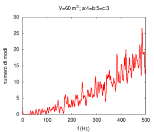
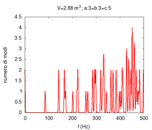
Therefore, the difference between two successive frequencies is inversely proportional to the volume of the room for a fixed integer triad. The following tables present the allowed frequencies in increasing order (observe that, in general, an increase in the values of n diminishes the distance between two successive frequencies) for an auditorium, a room and a "shower stall" (speed of sound is 343 m/s).
| modal density | ||||||||||||||||||||||||||||||||||||||||||||||||||||||||||||||||||||||||||||||||||||||||||||||||||||||||||||||||||||||||||||||||||||||||||||||||||||||||||||||||||||||||||||||||||||||||||||||||||||||||||||||
|---|---|---|---|---|---|---|---|---|---|---|---|---|---|---|---|---|---|---|---|---|---|---|---|---|---|---|---|---|---|---|---|---|---|---|---|---|---|---|---|---|---|---|---|---|---|---|---|---|---|---|---|---|---|---|---|---|---|---|---|---|---|---|---|---|---|---|---|---|---|---|---|---|---|---|---|---|---|---|---|---|---|---|---|---|---|---|---|---|---|---|---|---|---|---|---|---|---|---|---|---|---|---|---|---|---|---|---|---|---|---|---|---|---|---|---|---|---|---|---|---|---|---|---|---|---|---|---|---|---|---|---|---|---|---|---|---|---|---|---|---|---|---|---|---|---|---|---|---|---|---|---|---|---|---|---|---|---|---|---|---|---|---|---|---|---|---|---|---|---|---|---|---|---|---|---|---|---|---|---|---|---|---|---|---|---|---|---|---|---|---|---|---|---|---|---|---|---|---|---|---|---|---|---|---|---|---|
| auditorium A=30 m, B=50 m, C=10 m |
room A=4 m, B=5 m, C=3 m |
shower stall A=1.2 m, B=1.2 m, C=2 m |
||||||||||||||||||||||||||||||||||||||||||||||||||||||||||||||||||||||||||||||||||||||||||||||||||||||||||||||||||||||||||||||||||||||||||||||||||||||||||||||||||||||||||||||||||||||||||||||||||||||||||||
|
|
|
||||||||||||||||||||||||||||||||||||||||||||||||||||||||||||||||||||||||||||||||||||||||||||||||||||||||||||||||||||||||||||||||||||||||||||||||||||||||||||||||||||||||||||||||||||||||||||||||||||||||||||
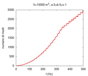
| In this case, the allowed frequencies are above the lower limit (20 Hz) of audible frequencies and are in a continuum. The room dimensions are such that no distinct frequency bands appear. It is for this reason that the causes of any dishomogeneity in the reflected sound field in auditoria are only partially due to the formation of stationary waves. |
In this case, the allowed frequencies are more distinctly separate and the frequency "gap" is small and close to the threshold of frequency discrimination of the human ear. The selective effect is, however, present and is more evident at low frequencies: it is the cause of the bad acoustics of certain school classrooms in which the teacher's voice is overpowered by a "boom" due to the formation of low-frequency stationary waves. Moreover, remember that higher frequency modes, even though permitted, decay much more quickly. |
In this case, allowed and well-separated bands are formed (i.e. sets of levels very close in frequency). Several of these bands fall exactly within the most common vocal range (from 300 to 500 Hz) making our "performances" in the shower rich with resonances. Moreover, observe that, due to the fact that two of the three chosen dimensions are identical, several different modes produce the same frequency. This is the phenomenon of degeneracy of energy levels, which is well-known to physicists studying quantum mechanics. |
||||||||||||||||||||||||||||||||||||||||||||||||||||||||||||||||||||||||||||||||||||||||||||||||||||||||||||||||||||||||||||||||||||||||||||||||||||||||||||||||||||||||||||||||||||||||||||||||||||||||||||
| resonance frequencies | ||||||||||||||||||||||||||||||||||||||||||||||||||||||||||||||||||||||||||||||||||||||||||||||||||||||||||||||||||||||||||||||||||||||||||||||||||||||||||||||||||||||||||||||||||||||||||||||||||||||||||||||
|
|
|
||||||||||||||||||||||||||||||||||||||||||||||||||||||||||||||||||||||||||||||||||||||||||||||||||||||||||||||||||||||||||||||||||||||||||||||||||||||||||||||||||||||||||||||||||||||||||||||||||||||||||||
In-depth study and links
- On the page Virtual laboratory: experiments on resonating cavities, you will find guided experiments to carry out with our 2D Wave Applet.
- On this page, we have dealt with the topic of environmental acoustics, albeit not thoroughly. We invite you to read the pages on sound reflection and sound diffraction for a more in-depth look at this subject.
- Many of the above-described phenomena depend on sound wave frequency. Therefore, it is important that you are aware of the range of musical instruments to understand the acoustic problems particular to each instrument of the orchestra.


