

Impedenza elettrica en
From "Physics, Waves, Music": a website about the physics of waves and sound, acoustics of musical instruments, musical scales, harmony and music.
| AI-translated from Italian. Original page: Impedenza_elettrica |
- The impedance of an electrical component is the ratio between the voltage applied across the component and the current flowing through it. In the mks system it is measured in ohms (1 Ω = 1 V/A)
- We are generally interested in the linear frequency response of the system, which means that we study the dynamics of the current when the applied voltage has a small amplitude and oscillates periodically in time (in particular sinusoidally).
- As observed for impedance in general, different components of the impedance are distinguished (resistance, capacitive reactance, inductive reactance) depending on whether the electrical energy is dissipated, or only transformed and stored in the component.
- For simplicity and clarity, in circuit diagrams each type of impedance is usually associated with a distinct elementary component, as briefly illustrated in the following section.
Elementary electrical elements
Resistor
- The resistor is the simplest dissipative electrical component.
- The simplest linear law governing its behaviour is Ohm's law, according to which the current flowing through an ideal resistor is directly proportional to the potential difference applied across it.
- The constant of proportionality R is called resistance, and is a constant characteristic of the particular nature and geometry of the resistor.
|
|

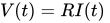
- The resistor introduces no phase shift between voltage and current, because the motion of the charge carriers inside it is practically instantaneous on a macroscopic scale. The current flowing through it dissipates as heat the energy coming from the potential difference, by the Joule effect.
- From the mechanical and acoustic point of view (see analogies in physics) the resistor is equivalent to the presence of viscous friction.
Capacitor
- The capacitor is an electrical element able to store the energy it receives in the form of an electric field inside it. It is the electrical analogue of a spring, which stores energy in the form of elastic potential energy.
- The storage of energy takes place in a characteristic time that depends on the nature and geometry of the capacitor. This is represented by a constant C called capacitance, and this is why, when subjected to a sinusoidal signal, the voltage across it and the current are not in phase with each other: the current leads the voltage by 90°

|
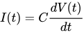
This relation shows that the current I in fact depends on the change in time of the potential difference V, and not on the instantaneous value of the potential difference V(t).
- When the potential difference across the capacitor does not change in time (DC, or direct current, regime), the capacitor reaches its state of maximum charge, after which it can no longer conduct. It therefore behaves as an open circuit for direct current.
- In the AC, or alternating current, regime, the capacitor has an impedance inversely proportional to the frequency of the signal: at low frequencies it has a large impedance, while at high frequencies (when the period of the alternating current is shorter than the charging time) it has a small impedance.
- That is, it tends to behave approximately as an open circuit at low frequencies, and as a short circuit at high frequencies. This frequency-selective power is the reason for its use in filters and in oscillating circuits.
Inductor
- The inductor is an electrical element able to store the energy it receives in the form of a magnetic field inside it. It is the electrical analogue of a mass, which stores energy in the form of kinetic energy.
- The storage of energy takes place in a characteristic time that depends on the nature and geometry of the inductor. This is represented by a constant L called inductance, and this is why, when subjected to a sinusoidal signal, the voltage across it and the current are not in phase with each other: the current lags the voltage by 90°

|
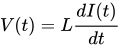
This relation shows that the voltage V across the inductor in fact depends on the change in time of the current I flowing through it, and not on the instantaneous value of the current itself.
- When the current through the inductor does not change in time (DC, or direct current, regime), the inductor reaches its state of maximum magnetic field, after which it can no longer store any more energy, and the current passes through it freely (apart from dissipative effects due to the fact that in general it also has a resistance). It therefore behaves as a short circuit for direct current.
- In the AC, or alternating current, regime, the inductor has an impedance directly proportional to the frequency of the signal: at low frequencies it has a small impedance, while at high frequencies (when the period of the alternating current is much shorter than the induction time) it has a large impedance.
- That is, it tends to behave approximately as a short circuit at low frequencies, and as an open circuit at high frequencies. This frequency-selective power is the reason for its use in filters and in oscillating circuits.
Category:
