Canna cilindrica en
Da "Fisica, onde Musica": un sito web su fisica delle onde e del suono, acustica degli strumenti musicali, scale musicali, armonia e musica.
Jump to navigation Jump to searchEigenfrequencies and bore length
A cylindrical bore open at both ends without any other holes is the simplest possible model of a wind instrument; e.g. many types of pipe organs are built this way. Moreover, this model is useful for describing some properties of instruments with cylindrical bores such as the flute and clarinet.
An air column made to vibrate within a tube functions basically as a sound wave guide. For frequencies that are not too high, the waves, which are excited at one end of the bore by a source of external energy, instead of propagating freely in space in spherical wave fronts, are confined within the tube and propagate parallel to the axis maintaining flat wave fronts (for exceptions to this, see the discussion on simplifying hypotheses and the following paragraph). Here we will not describe in detail the modes in which it is possible to make an air column oscillate. With regards to this, see the pages on Wind instruments.
The finite length L of the bore is the key element that makes a resonator highly selective and, therefore, a potential musical instrument. In fact, for a vibration to be sustained for the time necessary to be perceived as a sound, the waves that travel along the bore, reflected back and forth by the ends, must be able to create a stationary oscillation. The way in which stationary waves are formed is better examined on the pages dedicated to (stationary waves and one dimensional systems). Here we need only remember that the only stationary waves possible are those that have the correct behaviour at the ends.
What is this correct behaviour? This problem can be very complex for real musical instruments, as the end of the bore is a point in which acoustic impedance changes passing from the inside of the tube to the open air. In real cases, part of the acoustic energy is transferred from the bore to the environment and this is the very part that is then radiated into the surrounding space and that we can perceive as sound coming from the instrument. However, the passage from a confined vibration to a free one can be complex and the wave fronts can be diffracted at the edges of the bore.
To put it briefly, the passage from a flat wave front to a spherical one generally happens by degrees and through complex geometries and an accurate calculation of the effect of this passage on the eigenfrequencies of the bore is not elementary. However, we are analysing model instruments here and, therefore, we can begin with the simplest case.
Ideal open-open bore
In the idealised case of a non-radiating bore , the possible modes of oscillation corresponding to stationary waves are completely analogous to those of a vibrating string. In fact, pressure waves always have nodes at the ends of the tube because a node of acoustic pressure corresponds to a point in which the pressure of the medium remains unvaried and equal to the external atmospheric pressure. Therefore, the normal modes can be visualised like the normal modes of a string with the warning that the figures for the string can refer to the effective geometrical configuration of the string itself, while, in the case of the bore, since the oscillations of the air column are longitudinal and not transversal, they should be considered as an abstract graph representing sound pressure along the bore.
Therefore, in an ideal case, it is very easy to calculate the eigenfrequencies of the open bore without having to really solve the wave equation. The frequencies only depend on the length L of the bore and the speed of sound c. The minimum frequency, or fundamental of the bore, is the maximum wavelength compatible with the boundaries and equal to twice the length of the bore
- ,
while the upper frequencies are in a perfectly harmonic ratio with the fundamental
- .
| normal modes: red = sound pressure; green = air speed | |||
|---|---|---|---|

|

|

|

|
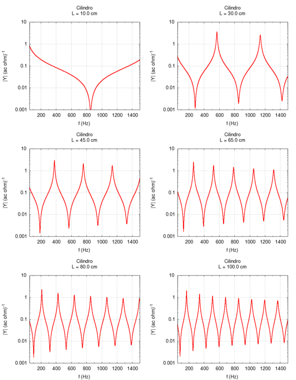
Using the language of impedance, we can study the response of the system to all of the frequencies in a single graph. We expect a response with narrow peaks in correspondence to the resonance frequencies and an attenuation of all other frequencies. In the intermediary points between the two resonances we find the weakest response or anti-resonance".
Ideal semi-open bore
When the bore is closed at one end, the boundary conditions change. In particular, as at the open end, there must be a pressure node (the pressure does not change because we assume that the external air is ideally, infinitely compliant), so at the closed end, there must be a speed node (because we assume that the closed wall is infinitely rigid). However, for plane waves, a pressure node is always a speed anti-node and vice versa, a speed node is a pressure anti-node. Similarly, for a semi-open bore, the possible frequencies correspond to stationary pressure waves that have an anti-node at the closed end and a node at the open end. The longest of these waves measures four times the length of the bore and, given that c is the speed of sound, its frequency is
- .
The other eigenfrequencies are odd multiples of this fundamental
- .
Theoretically, we can also study the case of a closed-closed bore but this does not have any particular acoustic interest, as it does not allow sound to radiate into the surrounding environment.
| normal modes: red = sound pressure; green = air speed | |||
|---|---|---|---|

|

|

|

|
Effect of friction and radiation
Let's now study slightly less ideal bores introducing the effects due to viscose friction and the radiation of sound by the bore one at a time. For the sake of simplicity we will refer to an open-open bore but our general conclusions can be applied equally to other cases.
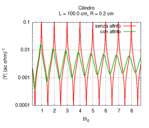
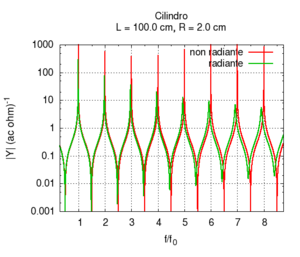
Note that the graph of the admittance gives more information about the response of the bore with respect to only the knowledge of the resonance frequencies. In particular, note that the admittance at high frequencies is progressively smaller than the admittance at low frequencies. In other words, the highest frequencies tend to be more attenuated with respect to low frequencies. This behaviour is partly due to the presence of viscose friction between air flow and the bore's walls. Viscose friction depends on the speed of the flow and, from the study of resonance, we know that it both strongly influences the amplitude of the peaks and weakly influences their position.
All the peaks of a completely ideal bore (i.e. without friction) would be infinite at the resonance frequencies. However, all real bores loose part of acoustic energy because of friction and, comparing the two responses displayed in the figure on the right, we note that, a part from attenuation, the presence of viscose friction also causes a small shift of the resonance frequencies towards lower values. However, this shift is not the same for all frequencies. This implies that, in the presence of friction, the response of the bore is not exactly harmonic. However, the deviations are very small. In the sample, we have chosen a bore with a small diameter because in this condition, the effect of friction is more relevant.
Contrarily to what happens with friction, the radiation of sound waves in the environment is enhanced when the bore has a large diameter. In this situation, the flat wave fronts at the end of the bore match spherical wave fronts that propagate in the open air. We can say that the impedance of the bore is better adapted to the impedance of radiation. In the example on the left, we can observe that the radiation produces a strong attenuation at high frequencies, however, the shape of the peaks remains both sharp and similar to an ideal one.
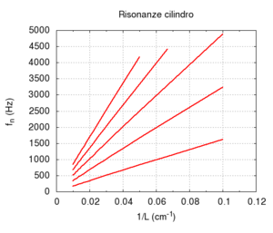
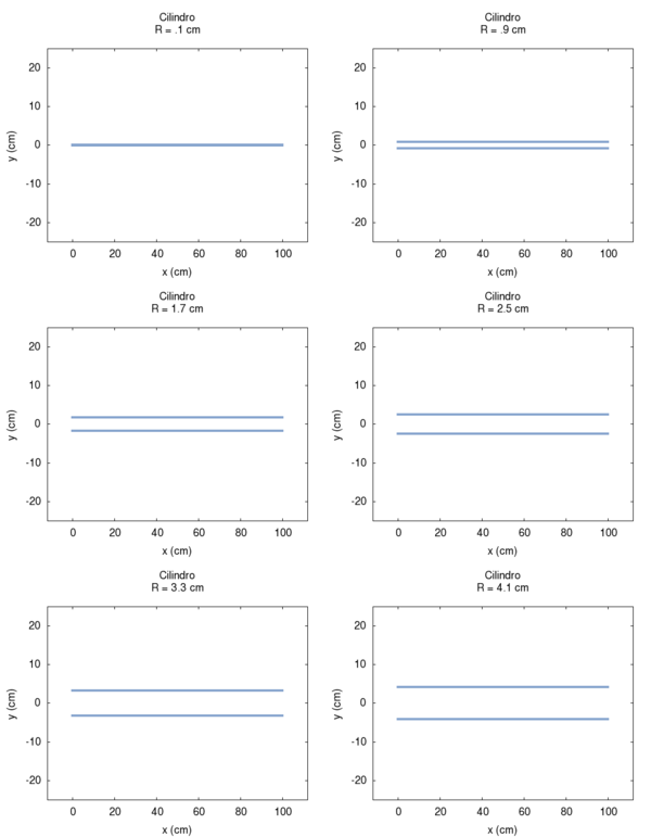
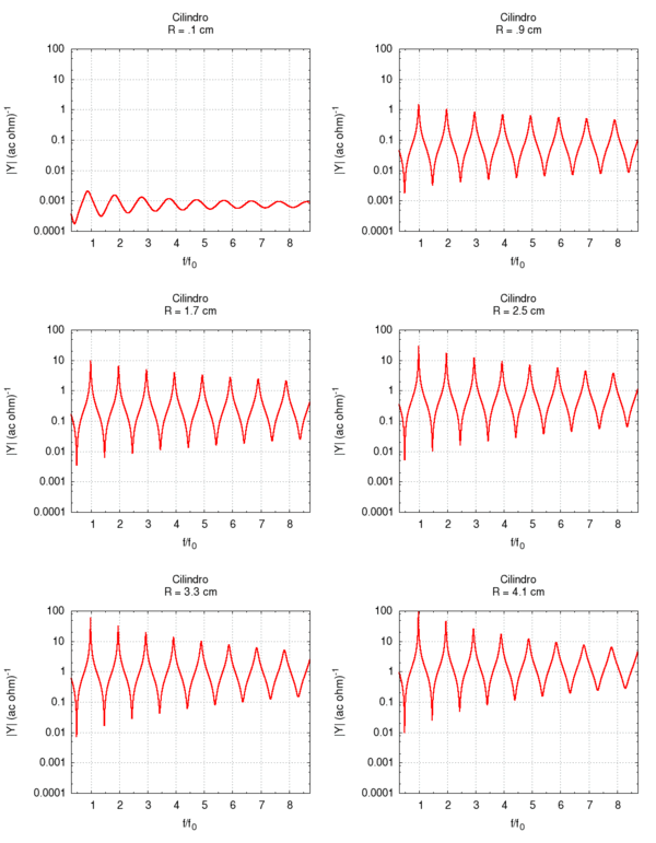
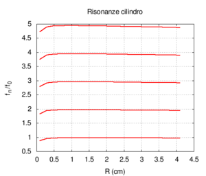
Of course, in real bores, both radiation and friction contribute simultaneously to the instrument's response. This case is better illustrated in the following graphs, in which the bore's response is calculated with a fixed length and a variable diameter and corrections for both friction and radiation are applied. Observing the position of the resonances in the rightmost image, we note a substantially wide, flat area at the extremes of which there are deviations due to, above all, the friction for small radii and radiation for large radii. The graph of the admittance shows a progressive increase for all values with the increase of the radius. This is predictable because a large calibre bore offers less resistance than a small calibre one. Even the shape of the peaks, very broad for small radii due to strong friction, looks more like the ideal non-damped response for large radii. We can also note the shift of the frequencies, first towards higher values due to the diminished friction and then slightly towards lower values, especially in the harmonics of a higher order. This shift is better highlighted in the rightmost image.
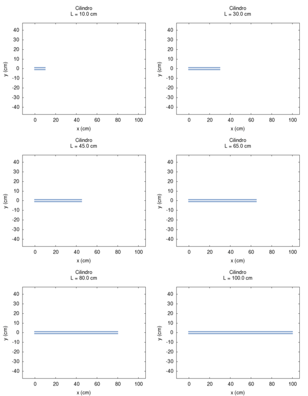
| Geometry | Acoustic response | Resonances |
|---|---|---|
|
|
|


